 |
|||
|
|
|||
|
|
|||
| ||||||||||
|
|
 When a specific torque value is required, the value
is listed in the SPECIFICATION section of the
S e r v i c e Manual. Tighten all other bolts and nuts
for general usage, hydraulic valve bodies, or
t a p e r l o c k studs to the torque values given in the
charts.
g. Locks.
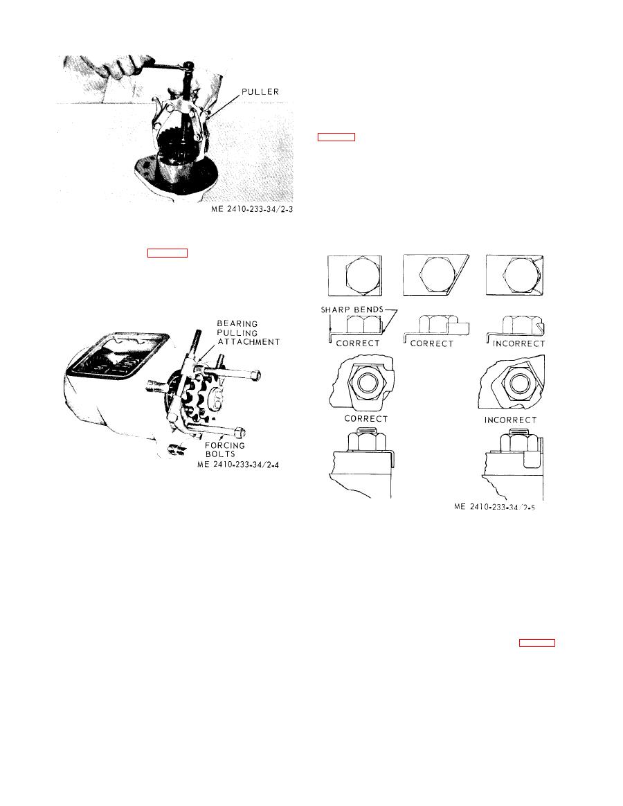
(1) Flat metal locks must be installed properly
a r o u n d the edge of the part. Bend the other end
against one flat-surface of the nut or bolt head.
( 2 ) Always install new locks in compartment
which house moving parts.
( 3 ) When installing lockwashers on housings
m a d e of aluminum, use a flat washer between the
lockwasher and the housing.
(2) B e a r i n g
pulling
attachment. B e a r i n g
pulling attachments (fig. 2-4) can be used with
T h e y can be used with Push Pullers to provide a
variety of pulling combinations.
e . Pressing Parts.
(1) When pressing one part into another, use
Fed, Spec. TT-A-580 Anti-Seize Compound to
l u b r i c a t e the m sting surfaces.
h. Lines and Wires. When removing o r
(2) Assemble tapered parts dry. Before
disconnecting a group of lines or wires, tag each one
a s s e m b l i n g parts with tapered splines, be sure the
t o assure proper assembly,
s p l i n e s are clean, dry and free from bum. Position
i. Shims. W h e n s h i m s a r e r e m o v e d , t i e t h e m
the parts together by hand to mesh the splines
together and identify them as to location. Keep
before applying pressure,
s h i m s clean and flat until they are reinstalled,
(3) If parts which are fitted together with
j. Bearings,
t a p e r e d splines are not tight, inspect the tapered
(1) Anti-friction
bearings.
s p l i n e s and discard if worn.
f. B o l t s a n d B o l t T o r q u e .
is removed, cover it to keep out dirt and abrasives.
(1) A bolt which is too long may "bottom'"
W a s h bearings in nonflammable cleaning solution
before the head is tight against the part it is to hold.
a n d allow them to drain dry. The bearing may be
.
T h e threads can be damaged when a "long" bolt is
dried with compressed air but DO NOT SPIN
removed.
THE BEARING.
( 2 ) If a bolt is too short, there may not be
(b) D i s c a r d t h e h e a r i n g s i f t h e r a c e s a n d
e n o u g h threads engaged to hold the part securely.
balls or rollers are pitted, scored or burned. If the
(3) Apply proper torque values to all bolts and
nuts when assembling Caterpillar equipment.
bearing is serviceable, coat it with oil and wrap it in
|
|
Privacy Statement - Press Release - Copyright Information. - Contact Us |
