 |
|||
|
|
|||
|
Page Title:
Section Ill. GENERAL MAINTENANCE |
|
||
| ||||||||||
|
|
 Chart
2-1.
Trouble-Continued
Probable Cause
Corrective Action
Malfunction
c.
Remove
valve
for
inspection
and
c.
Worn
poppet
on
valve
selector
repair
spool
a.
Remove
winch
for
inspection
and
17.
Winch
clutch
pressure
low
a. Broken seal ring on bevel gearshaft
repalce broken seal ring (para 3-
14).
b.
Damaged
preformed
packing
in
b.
Remove
winch
for
inspection
and
clutch
pack
replace
preformed
packing
Section Ill. GENERAL MAINTENANCE
General
This section provides direct support and general
s u p p o r t maintenance personnel with general repair
instructions applicable to the Caterpillar D-7F
tractor. T h e f o l l o w i n g i n s t r u c t i o n s w i l l p r o v e
helpful to disassemble and assemble the tractor
components.
Genera]
Instructions
a . Cleanliness.
(1) Whenever hydraulic, fuel, lubricating oil or
air lines are disconnected, clean the point of
disconnection and the adjacent area. As soon as the
disconnection is made, cap, plug or tape the line or
c . Disassembly and Assembly. W h e n a s s e m b l i n g
o p e n i n g to prevent entry of foreign material. The
a machine, complete each step in turn. Do not
same recommendations for cleaning and covering
partially assemble one part and start assembling
a p p l y when access covers or inspection plates are
other part. Make all adjustments as
some
removed.
recommended. Always check the job after it is
(2) Clean and inspect all parts. Be sure all
completed to see nothing has been overlooked.
passages and holes are open. Cover all parts to keep
d . Service Tools.
them clean. Be sure parts are clean when installed.
(1) Puller assembly (2 or 3 arm). Two or three
Leave new parts in their containers until ready for
arm puller assemblies (figs. 2-3 and 2-4) can be
assembly.
used to remove gears,
bearing
cages,
hubs,
b. Removal and Installation.
b e a r i n g s , shafts, etc.
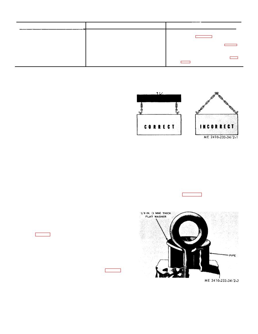
(1) Unless otherwise specified, all removals
s h o u l d be accomplished using an adjustable lifting
b e a m . All supporting members (chains and cables)
s h o u l d be parallel to each other and as near per-
pendicular as possible to the top of the object being
lifted (fig. 2-1).
(2) When it is necessary to remove a com-
ponent on an angle, remember that the capacity of
an eyebolt diminishes as the angle between the
supporting members and the object becomes less
than 90. Eyebolts and brackets should never be
bent and should only have stress in tension. A
length of pipe and a washer can be used (fig. 2-2),
t o help relieve these stresses on eyebolts.
( 3 ) Some removals require the use of lifting
fixtures to obtain proper balance and to provide
safe handling.
(4) If a part resists removal, check to be
c e r t a i n all nuts and bolts have been removed and
t h a t an adjacent part is not interfering.
|
|
Privacy Statement - Press Release - Copyright Information. - Contact Us |
