 |
|||
|
|
|||
|
|
|||
| ||||||||||
|
|
 TM 5-2410-233-23
FINAL DRIVE PINIONS AND FLANGES MAINTENANCE - CONTINUED
0101 00
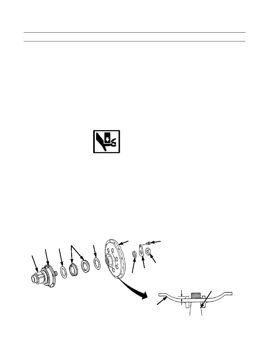
ASSEMBLY - CONTINUED
CAUTION
Duo-cone seal assembly is a two-piece seal. It must be used as a matched pair or failure will result. Do not separate.
5.
Install new packings (11) on retainers (10).
CAUTION
Seals and seal contact surfaces must be kept clean. Do NOT touch after being cleaned or leaks can result.
NOTE
Do NOT apply oil to packings.
6.
Install retainer (10) with packing (11) in bearing cage (4). Clean metal contact surface of seal, then apply a thin film of
clean oil to metal contact surface.
7.
Install retainer (10) with packing (11) in flange (1). Clean metal contact surface of seal, then apply a thin film of clean
oil to metal contact surface.
8.
Clean and dry splines on shaft of final drive pinion (6).
WARNING
Keep hands clear of puller when installing flange. Failure to do so could cause personal injury.
9.
Position flange (1) on splines of final drive pinion (6) shaft, install puller, and press flange on final drive pinion shaft
with a force of 35-40 tons (312-356 kn). Remove puller.
10.
Measure distance from shoulder on final drive pinion (6) shaft to hub face in center of flange (1). This distance must be
0.12 in. +/- 0.03 in. (3.15 mm +/- 0.80 mm).
11.
If distance in step 10 is less than 0.09 in. (2.29 mm), replace flange (1) and final drive pinion (4). If distance exceeds
0.15 in. (3.81 mm), remove flange and clean final drive pinion and shaft splines. Reinstall flange.
12.
Install new gasket (9) in hub of flange (1).
13.
Install lock (8) on flange (1) with capscrew (7).
NOTE
Nut (2) is tightened and lock (8) is bent to secure nut after final drive pinion and flange assembly is installed
in bevel gear case.
14.
Install nut (2) on shaft of final drive pinion (6) finger tight.
1
7
11
10
11
4
6
2
8
9
0.12 IN. +/- 0.03 IN.
(3.15 MM +/- 0.80 MM)
6
1
386-547
0101 00-5
|
|
Privacy Statement - Press Release - Copyright Information. - Contact Us |
