 |
|||
|
|
|||
|
Page Title:
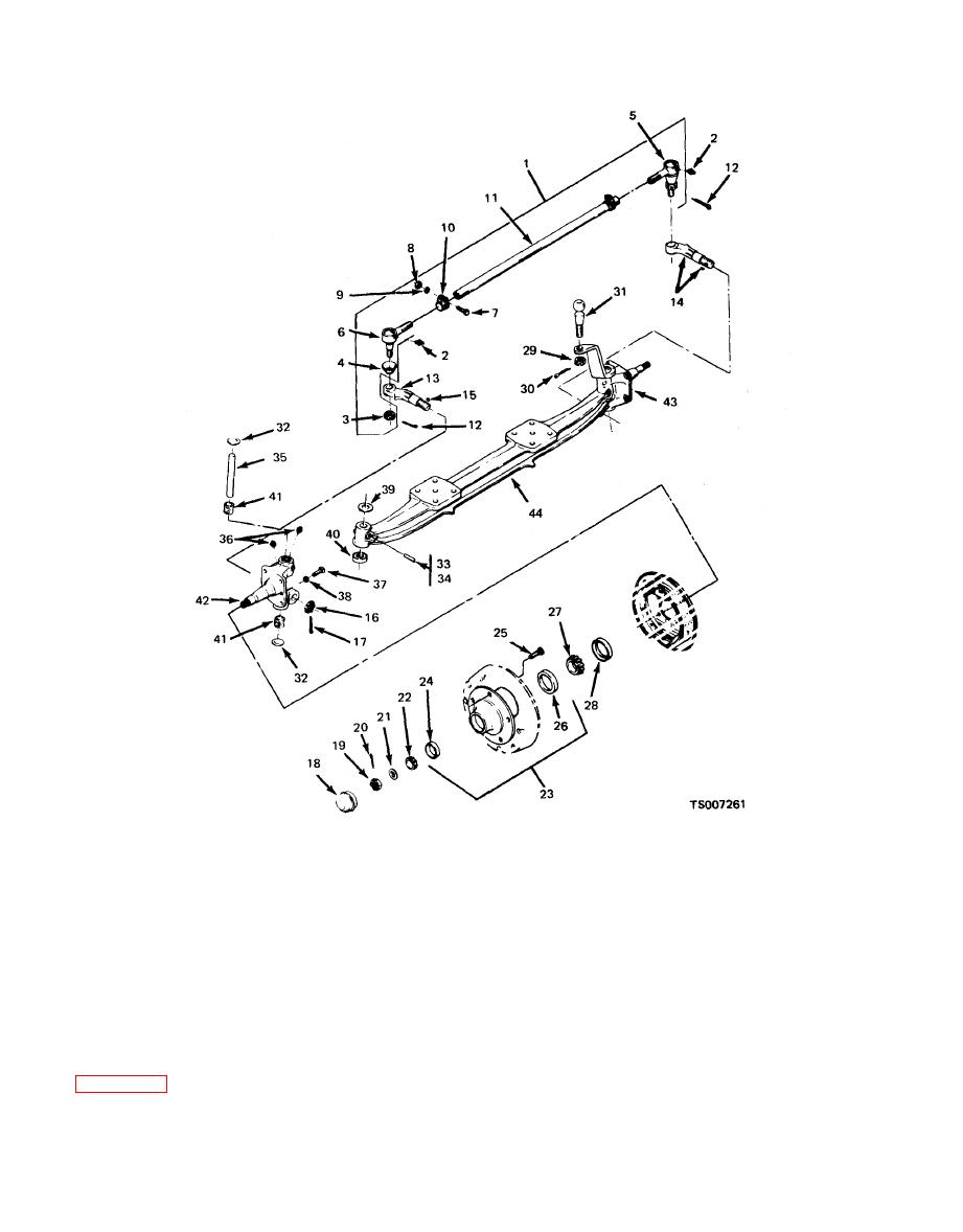
Figure 12-2. Front Axle Assembly. |
|
||
| ||||||||||
|
|
 TM 10-3930-633-34
34. Key
12. Cotter pin
23. Hub and cups
1. Axle assembly
13. Steering arm, R.H.
35. Knuckle pin
24. Cup, outer
z. Lube fitting
36. Lube fitting
14. Steering arm, L.H.
25. Stud, wheel
3. Hex nut
37. Capscrew
15. Woodruff key
26. Cup, inner
4. Dust cover
38. Hex nut
27. Cone
16. Hex nut
5. Tie rod end. R.H.
39. Shim
28. Seal
17. Cotter pin
6. Tie rod end. L.H.
40. Bearing
18. Hub cap
29. Nut
7. Capscrew
41. Bushing
30. Cotter pin
19. Hex nut
8. Hex nut
42. Steering knuckle, R.H.
31. Ball stud
20. Cotter pin
9. Lockwasher
43. Steering knuckle, L.H.
32. Plug
21. Washer
10. Clamp
44. Axle beam
22. Bearing cone
33. Key
11. Rod
( 4 ) Remove hub caps (18). Remove
(2) Remove tie rod and parts as outlined in
castellated nut (19), cotter pin (20) and bearing
cones (22) from each end of axle.
(3) Remove castellated nut, cotter pin and
ball stud from L. H. steering knuckle (43).
|
|
Privacy Statement - Press Release - Copyright Information. - Contact Us |
