 |
|||
|
|
|||
|
Page Title:
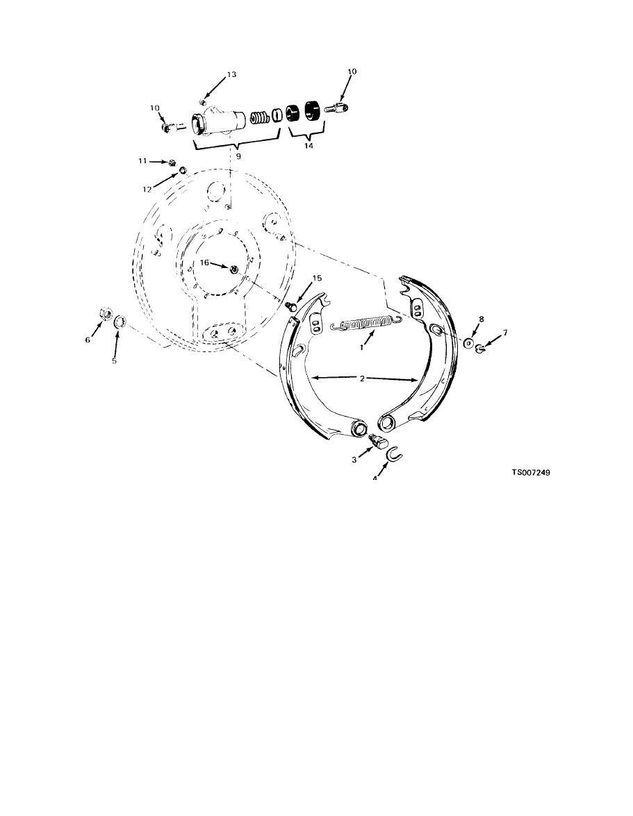
Figure 9-3. Rear Brake Assembly. |
|
||
| ||||||||||
|
|
 TM 10-3930-633-34
13. Bleeder screw
5. Lockwasher
9. Wheel cylinder assembly
1. Return spring
14. Cylinder kit
10. Pushrod
2. Shoe and lining
6. Hex nut
15. Capscrew
7. Cotter pin
11. Capscrew
3. Anchor pin
16. Hex nut
12. Lockwasher
4. Ring
8. Washer
(2) After cleaning, hold the cylinder casting
(1) Unhook return spring (1). Pull off clip (7)
up to a strong light and sight through the
and washer (8) from guide pin.
cylinder bore. Any blemishes such as pitting,
(2) Pull off ring (4) from each anchor pin (3),
visible wear patterns, etc., will necessitate unit
and remove the shoe and lining assemblies (2).
replacement.
(3) Remove cylinder pushrods (10). Remove
capscrews (11) and lockwashers (12), and lift off
(3) A hone may be used to "clean-up" the
cylinder, provided its use does not materially
wheel cylinder assembly (9). Remove bleeder
increase the size of the bore.
screw (13).
(4) Cylinder diameter must not exceed the
(4) Remove nut (6) and lockwasher (5) to
nominal dimension by more than 0.007 inch. This
remove anchor pin (3),
figure can be checked with a "GO-NO GO" type
(5) Backing plate is not to be removed from
gage or by inserting a piston into the cylinder and
axle unless damaged.
checking clearance with a wire gage.
c. Cleaning, Inspection, and Repair.
(1) Clean cylinder castings thoroughly with
(5) If mineral oil is present in the system, the
solvent, Federal Specification P-D-680.
|
|
Privacy Statement - Press Release - Copyright Information. - Contact Us |
