 |
|||
|
|
|||
|
|
|||
| ||||||||||
|
|
 TM 10-3930-633-34
manual lever and shaft from the transmission
case.
a. Disassembly.
(6) Tap the toggle lever sharply toward the
(1) Remove the stator support attaching
rear of the case to remove the plug and pin.
screws and remove the stator support. Mark the
(7) Remove the pawl pin by working the
top surface of the pump driven gear with Prussian
pawl back and forth. Remove the pawl and toggle
blue to assure correct assembly. Do not scratch
lever assembly, and then disassemble.
the pump gears.
(8) Remove the manual shaft seal and case
(2) Remove the drive and driven gears from
vent tube.
the pump body.
b. Assembly.
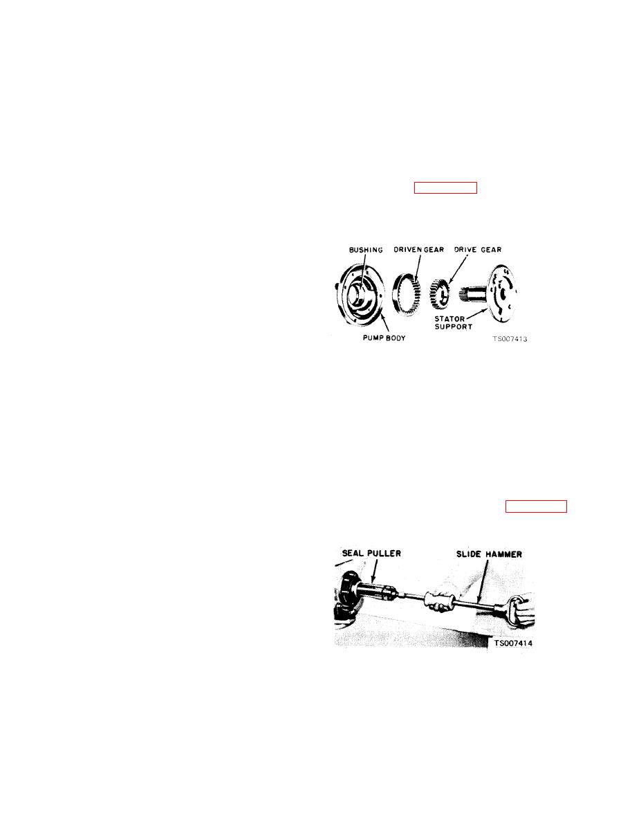
(3) Refer to figure 7-25 for a disassembled
(1) Coat the outer diameter of a new manual
view of the front pump. Inspect the pump body
shaft seal with sealer, then install the seal in the
housing, gear pockets and crescent for scores.
case with a driver.
(2) Install the vent tube in the transmission
case.
(3) Assemble the link to the pawl with the
pawl link pin, washer, and pawl return spring.
Assemble the toggle lever to the link with the
toggle link pin. Position the pawl return spring
over the toggle link pin, and secure it in place
with the washer and the small retainer clip. In-
stall the assembly in the transmission case by
installing the pawl pin and the toggle lever pin.
Install the torsion lever assembly. Position the
(4) If the front pump housing bushing
spring on the torsion lever with a screwdriver.
requires replacement, refer the unit to depot
Make certain that the short side of toggle does
maintenance.
not extend beyond the largest diameter of the ball
(5) If any parts other than the stator sup-
or the toggle lever pin. Tap the toggle lever in or
port, bushings or oil seal are found defective,
our as necessary to center the toggle lever on the
replace the pump as a unit. Minor burrs and
ball.
scores may be removed with crocus cloth. The
(4) Install the manual lever and shaft in the
stator support is serviced separately.
transmission case. Position the detent lever on
(6) Bolt the front pump to the transmission
the shaft, and secure it with a nut. Tighten the
case with capscrews.
nut to 20-- 30 ft/lbs torque. Rotate the manual
(7) If the oil seal requires replacement,
lever to the rear of the case. Position the detent
install the oil seal remover shown in figure 7-26.
spring in the case. Hold the detent plug on the
Then pull the front seal from the pump body.
spring with a 3/16 inch socket wrench, then
depress the spring until the plug is flush with the
case. Carefully rotate the manual lever to the
front of the case to secure the plug. A piece of thin
walled tubing may be used to depress the plug if a
small socket wrench is not available.
(5) Position the ends of the parking pawl
operating rod in the detent lever and toggle lift
lever, and secure with the two small retaining
pins,
(6) Install a new seal on the downshift lever
shaft, then install the lever and shaft in the case.
Position the inner downshift lever on the inner
end of the shaft with the mark 0 facing toward the
(8) Clean the pump body counterbore. Then
center of the case. Install the lockwasher and nut,
inspect the bore for rough spots. Smooth up the
then tighten the nut to 17 20 ft/lbs torque.
counterbore with crocus cloth.
(7) Check the operation of the linkage. The
linkage should operate freely without binding.
|
|
Privacy Statement - Press Release - Copyright Information. - Contact Us |
