 |
|||
|
|
|||
|
|
|||
| ||||||||||
|
|
 TM 10-3930-633-34
(5) Check the actuating lever for free
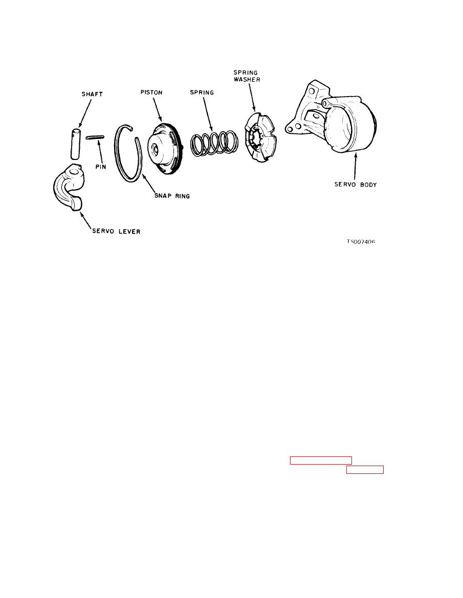
(2) Press down on the servo piston, and
movement.
remove the snap ring. Release the pressure on the
e. Installation.
piston slowly to prevent the spring from flying
out .
(1) TO install the rear servo, position the
servo anchor strut on the servo band, and rotate
(3) Remove the piston, servo spring, and
the band to engage the strut.
spring washer.
c. Inspection.
(2) Hold the servo anchor strut in position
with the fingers, position the actuating lever
(1) Inspect the servo body for cracks and the
strut, and install the servo.
piston bore for scores.
(3) Install but do not tighten the servo
( 2 ) Check the fluid passages for ob-
attaching bolts. The longer bolt must be installed
structions.
in the inner bolt hole.
(3) Inspect the band and the struts for
(4) Move the rear servo (with reasonable
distortion. Inspect the band ends for cracks.
force) toward the centerline of the transmission
(4) Inspect the servo spring for distortion.
case, against the servo attaching bolts. While
(5) Inspect the band lining for excessive
holding the servo in this position, torque the
wear and bonding to the metal band.
attaching bolts to specification.
(6) Check the servo body to case mating
(5) Install the two front servo tubes and the
surface for burrs. Check the actuating lever
control valve body. Check the clearance between
socket for scores.
the manual valve and the manual lever actuating
(7) Replace seals that are damaged.
pin as given in paragraph 7-13.
d. Assembly.
(6) Adjust the rear band (para. 7-5).
(1) Install a new seal ring on the servo
(7) Install the fluid screen and pan, and fill
piston.
the transmission with fluid.
(2) Install the piston in the servo body.
Lubricate the parts to facilitate assembly. Install
the servo spring with the small coiled end against
a. Remoual
the servo piston.
(1) Remove the parking brake drum and
(3) Compress the spring with a C-clamp.
companion flange attaching nut.
Then install the snap ring. The snap ring must be
(2) With a sharp chisel, remove the seal from
fully seated in the groove.
the extension housing. Do not allow metal chips
(4) Install the actuating lever shaft, aligning
to enter the output shaft bearing.
the retaining pin holes, and install the pin.
|
|
Privacy Statement - Press Release - Copyright Information. - Contact Us |
