 |
|||
|
|
|||
|
|
|||
| ||||||||||
|
|
 TM 10-3930-633-34
(11) Install the inhibitor valve spring and
assembly by tapping it gently with a soft ham-
valve in the lower body.
mer.
(7) Install the compensator pressure tube to
(12) Install the 1-2 shift valve spring and
the pressure regulator and the control valve body.
valve. Install the lower body side plate.
(8) Turn the manual valve one full turn in
(13) Install the compensator cutback valve
each manual lever detent position. If the manual
in the upper body. Install the upper body rear
valve binds against the actuating pin in any
plate.
detent position, loosen the valve body attaching
(14) Install the downshift valve and spring
bolts and move the body away from the center of
in the body.
the case. Move the valve body only enough to
(15) Install the throttle boost valve and
relieve the binding. Torque the attaching bolts
spring. Install the throttle boost short valve and
and ret-heck the manual valve for binding.
sleeve.
(9) Position the pushrod in the bore of the
(16) Install the compensator valve, inner
vacuum diaphragm unit, Using the diaphragm
and outer compensator springs, and the com-
unit as a guide, insert the pushrod into the
pensator sleeve and plug.
t h r e a d e d opening of the case. Torque the
(17) Position the front plate. Apply pressure
diaphragm unit to 1523 ft/lbs. Connect the
to the plate while installing the two attaching
screws.
vacuum hone.
(10) Torque the front servo attaching bolts
(18) Install the throttle valve, plug and
check valve in the throttle valve body, Position
to 3035 ft/lbs.
(11 ) Adjust the front band (paragraph 7-5).
the separator on the upper body and install the
throttle valve body. Install the three attaching
(12) Install the fluid screen and the screen
retaining clip.
screws.
(19) Install four screws attaching the cover
(13) Position a new pan gasket on the
to the lower body, two screws attaching the
bottom of the transmission case, and install the
separator plate to the upper body, and one screw
pan. Torque the pan screws to 1013 ft/lbs.
attaching the separator plate to lower body.
(14) Adjust the rear band (para 7-5).
Torque the cover and body screws to 20 30
7-14. Front Servo
in./lbs.
a. Removal.
(20) Install the manual valve.
(1) Drain the fluid from the transmission,
e. Installation.
and remove the pan and fluid screen.
(1) Before installing the control valve body,
(2) Remove the vacuum diaphragm unit.
check for a bent manual valve by rolling it on a
(3) Loosen the three control valve body
flat surface,
attaching bolts.
(2) Install the control valve body by aligning
(4) Remove the attaching bolts from the
the front servo tubes with the, holes in the valve
front servo (fig, 7-14). Hold the strut with the
body. Shift the manual lever to the 1 detent, and
fingers and remove the servo.
place the inner downshift lever between the
b. Disassembly.
downshift lever stop and the downshift valve. The
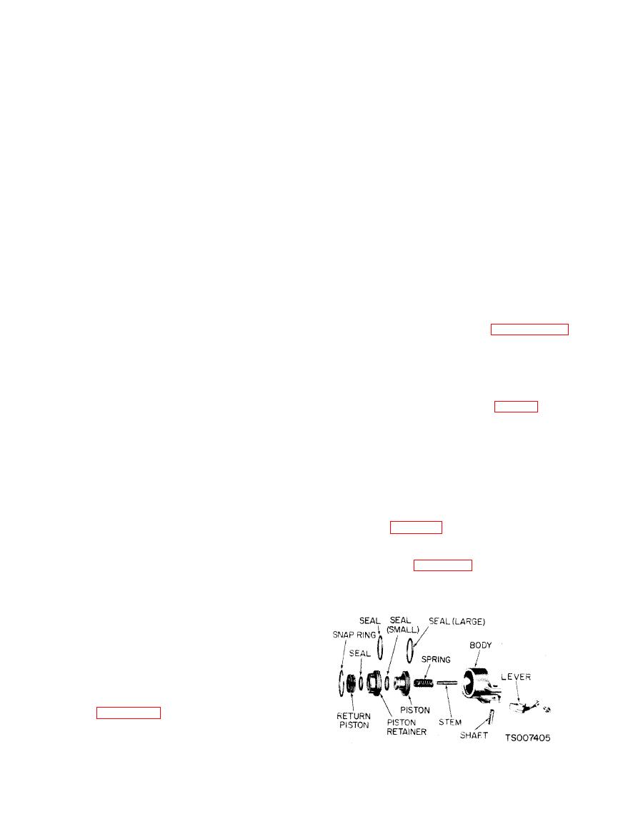
(1) Refer to figure 7-17 and remove the servo
manual valve must engage the actuating pin in
piston retainer snap ring. Apply pressure to the
the manual detent lever.
piston when removing the snap ring.
(3) Install but do not tighten the control
valve body attaching bolts.
(4) Move the control valve body toward the
center of the case until the clearance is less than
0,050 inch, between the manual valve and the
actuating pin on the manual detent lever.
(5) Torque t h e attaching bolts to
specification. Be sure that the rear fluid screen
retaining clip is installed under the valve body as
shown in figure 7-14.
(6) Install the main pressure oil tube. Be
sure to install the end of the tube that connects to
the pressure regulator first. Then, install the
other end of the tube into the main control valve
|
|
Privacy Statement - Press Release - Copyright Information. - Contact Us |
