 |
|||
|
|
|||
|
Page Title:
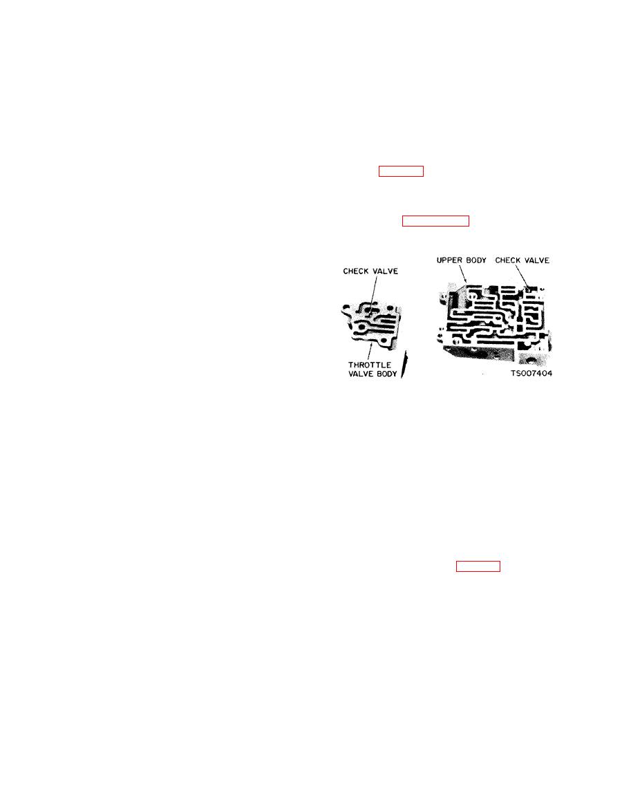
Figure 7-16. Check Valve Locations. |
|
||
| ||||||||||
|
|
 TM 10-3930-633-34
all valves and plugs for free movement in their
plug, and remove the compensator valve springs.
respective bores. Valves and plugs, when dry,
Remove the compensator valve.
m u s t fall from their own weight in their
(5) Remove the throttle boost short valve
respective bores.
and sleeve. Remove the throttle boost valve
(4) Roll the manual valve on a flat surface to
spring and valve.
(6) Remove the downshift valve and spring.
check it for a bent condition.
(7) Remove the upper valve body rear plate.
d. Reassembly.
(8) Remove the compensator cut back valve.
(1) Arrange all parts in their correct
(9) Remove the lower body side plate. The
positions (fig. 7-15) Rotate the valves and plugs
plate is spring-loaded. Apply pressure to the plate
when inserting them in their bores to avoid
while removing the attaching screws.
shearing of soft body castings.
(10) Remove the 1-2 shift valve and spring.
(2) Place the check valve in the upper body
Remove the inhibitor valve and spring.
as shown in figure 7-16. Then, position the
(11) Remove the two screws attaching the
separator plate on the body.
separator plate to the cover. Remove the lower
body end plate. The end plate is spring-loaded.
Apply pressure to the plate while removing the
attaching screws.
(12) Remove the low servo lockout valve,
low servo modulator valve and spring.
(13) Remove the 2-3 delay and throttle
reducing valve sleeve, the throttle reducing valve,
spring, and the 2-3 shift delay valve. The
reducing valve sleeve is lightly staked in the valve
body bore. To remove the sleeve, use a blunt
instrument against the end of the 2-3 shift valve
and push the sleeve from its bore. Remove the 2-3
shift valve spring, spring retainer and valve.
(3) Position the lower body on the upper
(14) Remove the transition valve spring and
body, and start but do not tighten the attaching
valve.
screws.
(4) Position the cover and separator plate on
(15) Remove the plate from the valve body
the lower body. Start the four through bolts.
cover.
(5) Align the separator with the upper and
(16) Remove the check ball spring and check
lower valve body attaching bolt holes. Install and
ball. Remove the 3-2 kickdown control valve
torque the four valve body bolts to 20 -- 30
spring and valve.
in./lbs. Excessive tightening of these bolts may
(17) Remove the 1-2 shift accumulator valve
distort the valve bodies, causing valves or plugs
spring retainer from the cover. Remove the
to stick.
spring, 1-2 shift accumulator valve and 1-2 shift
(6) Install the 3-2 kickdown control valve
accumulator lockout valve.
and spring and the check ball and spring in the
(18) Remove the through bolts and screws.
cover. Install the plate (fig. 7-15).
Then, separate the bodies. Remove the separator
(7) Insert the 1-2 shift accumulator lockout
plates from the valve bodies and cover. Be careful
valve, 1-2 shift accumulator valve, and spring in
not to lose the check valves.
the cover. Install the valve spring retainer.
c. Cleaning and Inspection.
(8) Install the transition valve and spring in
(1) Clean all parts thoroughly in clean
the lower body.
solvent, and then blow them dry with moisture-
(9) Install the 2-3 shift valve, spring retainer
free compressed air.
and spring. Install the 2-3 shift delay valve and
(2) Inspect all valve and plug bores for
the spring and throttle reducing valve in the
scores. Check all fluid passages for obstructions.
sleeve. Slide the sleeve and valve into position in
Inspect the check valve for free movement. In-
the lower body. Do not restake the sleeve.
spect all mating surfaces for burrs or distortion.
(10) Install the low servo lockout valve
Inspect all plugs and valves for burrs or scores.
spring. Install the low servo modulator and low
Crocus cloth can be used to polish valves and
servo lockout valves. Install the lower body end
plugs if care is taken to avoid rounding the sharp
plate.
edges of the valves and plugs.
(3) Inspect all springs for distortion. Check
|
|
Privacy Statement - Press Release - Copyright Information. - Contact Us |
