 |
|||
|
|
|||
|
Page Title:
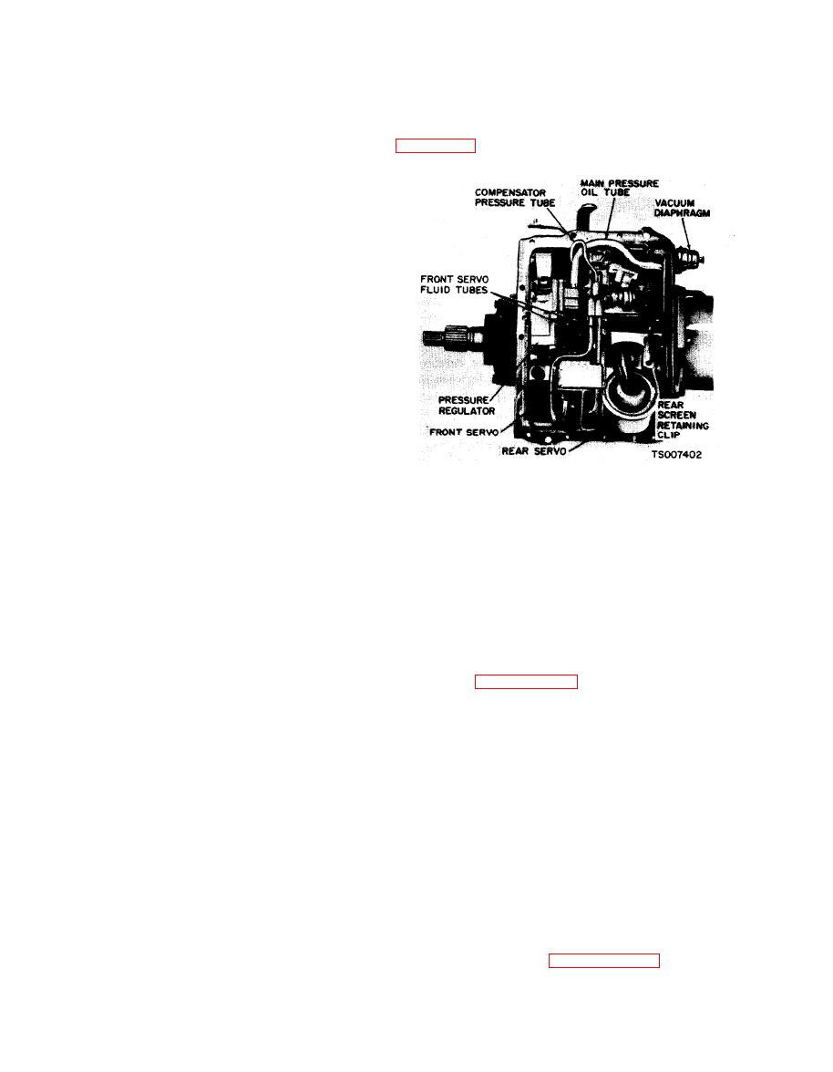
Figure 7-14. Control Valve Body Installed. |
|
||
| ||||||||||
|
|
 TM 10-3930-633-34
(48) Torque the attaching bolts to 8 - 10
(34) Measure and record the end play be-
ft/lb. Be sure that the rear fluid screen retaining
tween the front of the case and the large internal
clip is installed under the valve body as shown in
gear by prying between the front clutch cylinder
and the case. This end play should be 0.010-
0.029 inch. Total end play including the output
shaft, must not exceed 0.044 inch.
(35) Remove the dial indicator and install
the fourth pump mounting bolt. Torque all four
bolts to 17 - 22 ft/lb.
(36) Position the front band forward in the
case with the band ends up.
(37) Position the servo strut with the slotted
end aligned with the servo actuating lever, and
the small end aligned wit h the band end. Rotate
the band, strut, and servo into position engaging
the anchor end of the band with the anchor pin in
the case.
(38) Locate the servo on the case, and install
the attaching bolts. Tighten the attaching bolts
only 2 or 3 threads.
(39) Install the servo tubes.
(40) Position the servo anchor strut, and
rotate the rear band to engage the strut.
(41) Position the servo actuating lever strut
with a finger, and then install the servo and
(49) Turn the manual valve one full turn in
attaching bolts. Move the servo (with reasonable
each manual lever detent position. If the manual
force) toward the centerline of the case, against
valve bin ds against the actuating pin in any
the attaching bolts. While holding the servo in
detent position, loosen the valve body attaching
this position, torque the attaching bolts to 30 - 35
bolts and move the body away from the center of
ft/lb.
the case. Move the body only enough to relieve
(42) Install the pressure regulator body and
the binding. Torque the attaching bolts and
attaching bolts, and torque the bolts to 17 - 22
check the manual valve for binding.
ft/lb.
(50) Torque the front servo attaching bolts
(43) Install the control and converter valve
to 30 - 35 ft/lb.
guides and springs. Install the spring retainer.
(51) Adjust the front and rear bands as
(44) Install the control valve assembly,
detailed in paragraph 7-5.
carefully aligning the servo tubes with the control
(52) Position the control rod in the bore of
valve. Align the inner downshift lever between
the vacuum diaphragm unit and install the
the stop and the downshift valve. Shift the
diaphragm unit. Make sure the control rod enters
manual lever to the 1 position. Align the manual
the throttle valve as the vacuum unit is installed.
valve with the actuating pin on the manual detent
(53) Torque the diaphragm unit to 15-23 ft.
lever. Do not tighten the attaching bolts.
lb.
(45) Install the main pressure oil tube. Be
(54) Position the fluid screen under the rear
sure to install the end of the tube that connects to
clip and over the front pump inlet tube. Press the
the pressure regulator assembly first. Then,
screen down firmly. Install the screen retaining
install the other end of the tube into the main
clip.
control assembly by tapping it gently with a soft
(55) Place a new gasket on the transmission
hammer.
case and install the pan. Install the attaching
(46) Install the small control pressure
bolts and lockwashers and torque the bolts to 10-
c o m p e n s a t o r tube in the valve body and
13 ft/lbs.
regulator.
(56) If the converter and converter housing
(47) Move the control valve body toward the
were removed from the transmission, install these
center of the case until the clearance is less than
components. Refer to paragraph 7-11.
0.050 inch between the manual valve and the
actuating pin on the manual detent lever.
|
|
Privacy Statement - Press Release - Copyright Information. - Contact Us |
