 |
|||
|
|
|||
|
Page Title:
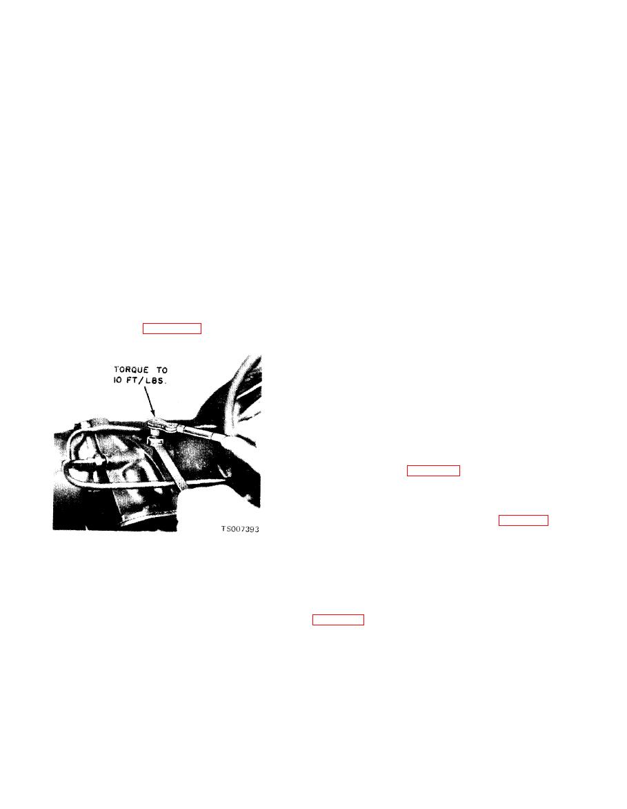
Figure 7-4. Rear Band Adjustment. |
|
||
| ||||||||||
|
|
 TM 10-3930-633-34
(5) Install the socket handle on the 9/16 inch
screw and tighten until the wrench clicks and
socket.
breaks.
(6) Insert the T-handle extension through the
(5) Back off the adjusting screw 1- turns.
s o c k e t handle and socket, and install the
Hold the adjusting screw stationary and tighten
screwdriver socket on the T-handle extension.
the adjusting screw locknut to specification.
Severe damage may result if the adjusting screw
(7) Place the tool on the adjusting screw so
that the screwdriver socket engages the screw and
is not backed off exactly 1 turns.
the 9/16 inch socket engages the locknut.
(8) With a torque wrench on the T-handle
a. Start the engine to allow it to reach its
extension, tighten the adjusting screw to 10
normal temperature. Apply both the parking and
in./lbs torque.
service brakes while making tests.
(9) Remove the spacer and tighten the ad-
b. The stall test is made in D, or R, at full
justing screw an additional turn. Hold the
throttle to check engine performance, converter
adjusting screw stationary, and torque the
clutch operation or installation, and the holiday
locknut to specification.
ability of the forward clutch, reverse-high clutch
(10) Place a new gasket on the pan, and
and low-reverse band and the gear train one-way
install the screen and pan on the transmission.
clutch. While making this test, do not hold the
(11) Fill the transmission with fluid. See LO
throttle open for more than five seconds at a time.
10-3930-633-12.
Then move the selector lever to Neutral and run
b. Rear Band Adjustment.
engine at 1000 RPM for about 15 seconds to cool
(1) Remove all dirt from adjusting screw and
the converter before making the next test. If the
surrounding area. See figure 7-4.
engine speed recorded by the tachometer exceeds
the maximum limits, 1300 to 1500 RPM, release
the accelerator immediately because clutch or
band slippage is indicated.
a. When performing control pressure checks,
make certain that the engine is at normal
operating temperature and that timing and
carburetor are properly adjusted. Set parking
brake firmly to prevent vehicle motion. Check
manifold vacuum (see Chapter 6) to make certain
a reading of 18 inches (Hg) is obtained at engine
idle. At higher altitudes, it may not be possible to
obtain 18 inches of vacuum; under these con-
ditions, use the chart in the lower part of table 7-2
to adjust pressure readings in proportion to the
lower vacuum readings. Make certain, however,
Figure 7-4. Rear Band Adjustment.
that the lower vacuum reading is not due to a leak
(2) Loosen the adjusting screw locknut with a
in the transmission or distributor vacuum line.
box end wrench as shown in the illustration.
b. With vacuum readings and engine ad-
(3) Using a torque wrench, tighten the ad-
justments verified, connect a pressure gage of O-
justing screw to 10 ft/lbs. Try to get the ad-
250 PSI range to the control pressure port shown
justment as close to exactly 10 ft/lbs as possible.
in figure 7-5, and proceed with test as follows:
(4) If the screw is found to be tighter than
wrench capacity (10 ft/lbs torque), loosen the
|
|
Privacy Statement - Press Release - Copyright Information. - Contact Us |
