 |
|||
|
|
|||
|
Page Title:
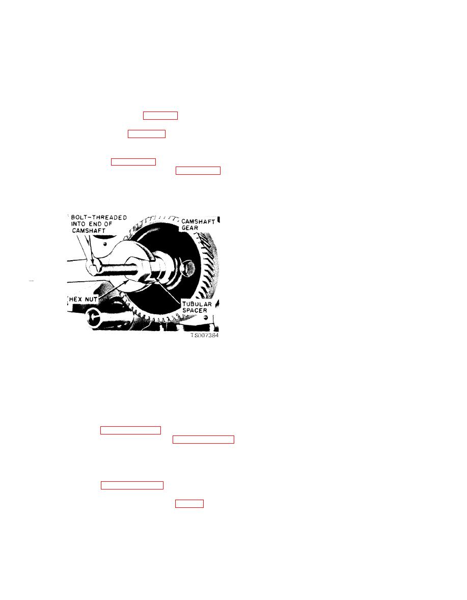
Figure 6-55. Installing Camshaft Gear. |
|
||
| ||||||||||
|
|
 TM 10-3930-633-34
(9) Clean the valve pushrod cover and
b. Installation. If the camshaft end play,
c y l i n d e r block gasket surfaces. Apply oil-
timing gear backlash and/or timing gear runout
resistant sealer to one side of a new gasket and
were excessive, make the necessary corrections
place the gasket on the pushrod cover with the
before installing the camshaft.
cemented side next to the cover. Install the cover
(1) Oil the camshaft bearing journals and
and torque the bolts in sequence to specifications.
apply Lubriplate or equivalent to all the lobes.
(10) Apply Lubriplate or equivalent to the
(2) Install the camshaft, gear and thrust
valve pad on the rocker arms. Oil the valve stems
plate as an assembly, making sure that the timing
with heavy engine oil. Align the valve rocker
marks are in alignment (fig. 6-36).
arms with the valves and pushrods. Tighten the
(3) Torque the thrust plate attaching screws
rocker arm stud nuts sufficiently to hold the
to specifications (see table 6-3).
pushrods in place. Adjust the valve clearance
( 4 ) Position the camshaft gear on the
following instructions given in TM 10-3930-633-
camshaft. Align the timing marks on the timing
12.
gears as shown in figure 6-36. Install the cam-
(11) Clean the valve rocker arm cover and
shaft gear with the tool shown in figure 6-55. Be
cylinder head gasket surface. Place the new
sure the gear and spacer are tight against the
gasket in the cover making sure that the tabs of
shoulder on the camshaft.
the gasket engage the notches provided in the
cover. Install the cover and torque the screws in
sequence to specifications.
(12) Set the distributor rotor so the points are
about to open for No. 1 cylinder firing position.
Install the distributor. Check the points. If the
camshaft timing marks are still aligned (step 6
above), the points should be fully open in No. 1
cylinder firing posit ion. If the points are not open,
remove the distributor and rotate the shaft in the
proper direction. Install the distributor and hold-
down clamp.
(13) Install the distributor cap and spark
plug wires as an assembly. Connect the spark
plug wires to the plugs and the secondary high
tension wire to the coil.
Inspection
(5) Crank the engine until the timing marks
a. Cleaning.
are aligned. Do not turn the crankshaft again
(1) Clean the camshaft in a bath of solvent,
until the distributor is installed.
Federal Specification P-D-680, and wipe dry.
(6) Clean the cylinder front cover and
(2) Clean timing gears in solvent bath and
cylinder block gasket surfaces. Install a new oil
dry with compressed air.
seal in the cylinder front cover. Clean the
b. Inspection.
crankshaft damper and inspect it, following the
(1) Inspect the gear teeth for scores, nicks,
procedures in paragraph 6-30. Install the cylinder
etc. Note the condition of the teeth contact
front cover and damper following paragraph 6-36.
pattern. If the teeth are scored, replace the gears.
(7) Clean the oil pump screen. Clean the oil
(2) It is not necessary to replace the gears in
pan and the gasket surfaces of the cylinder block.
sets. Replace the camshaft gear and check the
Install the oil pump screen and inlet tube and oil
b a c k l a s h , runout, etc., to determine if the
pan, following the procedures under Oil Pan
crankshaft gear should be replaced.
Installation, paragraph 6-43.
(3) Inspect the camshaft lobes for scoring
(8) Lubricate the valve lifters with heavy
and signs o f abnormal wear. L o b e wear
engine oil and install the lifters (fig. 6-6) in the
characteristics may result in pitting in the general
same bores from which they were removed. Apply
area of the lobe toe. This pitting is not
Lubriclate or equivalent to both ends of the
detrimental to the operation of the camshaft;
pushrods and install the pushrods in the same
therefore, the camshaft should not be replaced
sequence that they were removed. Be sure the
pushrods were seated in the valve lifter sockets.
|
|
Privacy Statement - Press Release - Copyright Information. - Contact Us |
