 |
|||
|
|
|||
|
Page Title:
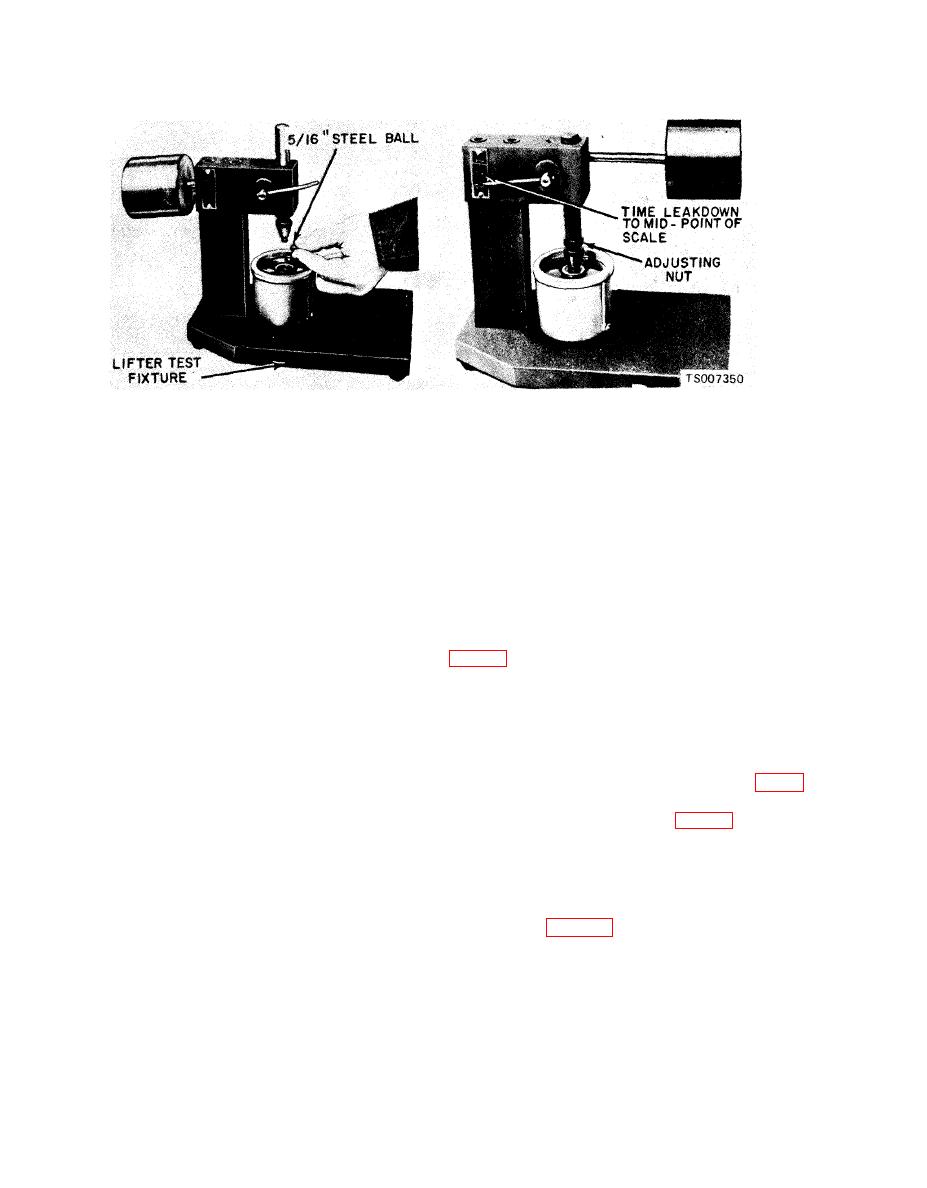
Figure 6-21. Testing Hydraulic Lifter, |
|
||
| ||||||||||
|
|
 TM 10-3930-633-34
(3) Place the valve lifter in the tester, with
the plunger facing upward. Pour hydraulic tester
a. General. After refacing valve seats and
fluid into the cup to a level that will cover the
checking all valve train parts as outlined in
valve lifter assembly. The fluid can be purchased
previous paragraphs, install valves as outlined
from the manufacturer of the tester. Do not use
below. Lubricate valve guides and valve stems
kerosene, for it will not provide an accurate test.
with heavy engine oil. Apply Lubriplate or
(4) Place a 5/16 inch steel ball in the plunger
equivalent compound to the tips of the valve
cup.
stems.
b. Installation.
(5) Adjust the length of the ram so that the
(1) Install each valve in the valve guide from
pointer is 1/16 inch below the starting mark when
which it was removed or to which it was fitted.
the ram contacts the valve lifter plunger to
(2) Oil and install a new intake valve oil seal
facilitate timing as the pointer passes the start
timing mark. Use the center mark on the pointer
the exhaust valves at this time.
scale as the stop timing instead of the original
(3) Install the valve spring over the valve. Be
stop timing mark at the top of the scale.
sure the closed coil end is placed against the
(6) Work the valve lifter plunger up and
cylinder head.
down until the lifter fills with fluid and all traces
(4) Position the spring retainer on all valve
of air bubbles have disappeared.
springs. Make sure that a positive rotating
(7) Allow the ram and weight to force the
retainer is used on all of the exhaust valves (fig. 6-
valve lifter plunger downward. Measure the exact
9).
time it takes for the pointer to travel from the
(5) Compress the spring (fig. 6-8). Apply
start timing to the stop timing marks on the
engine oil to the O-ring type seal, then install it on
tester.
(8) A valve lifter that is satisfactory must
the exhaust valve. Install the retainer locks.
have a leak-down rate (time in seconds) within 5
(6) Measure the assembled height of the
valve spring from the surface of the cylinder head
to 50 seconds at 1/16 inch plunger travel.
(9) If the valve lifter is not within
spring pad to the underside of the spring retainer
specifications, replace it with a new lifter. It is not
with dividers (fig. 6-22).
necessary to test a new lifter before installing it in
the engine.
|
|
Privacy Statement - Press Release - Copyright Information. - Contact Us |
