 |
|||
|
|
|||
|
Page Title:
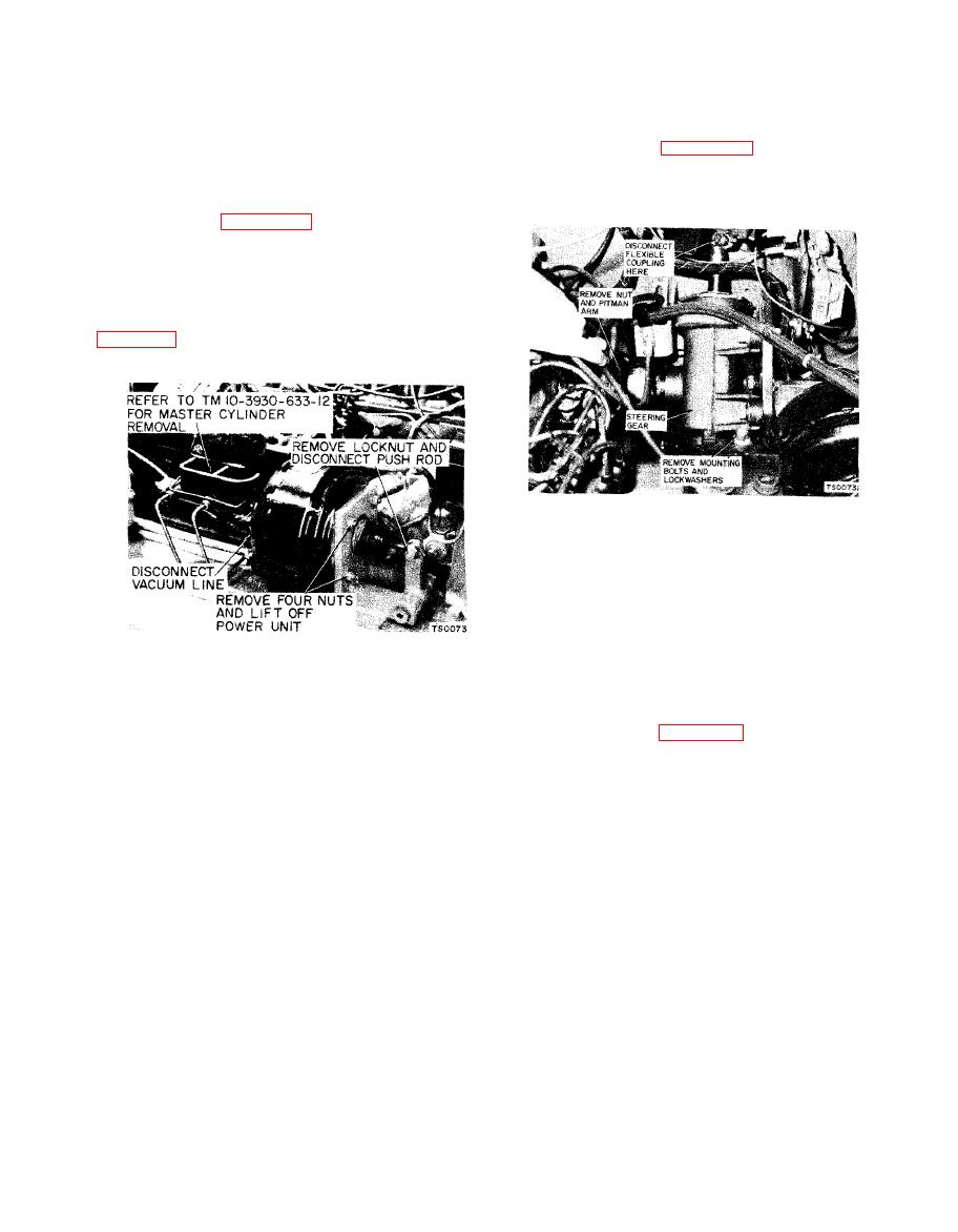
Vacuum Power Unit |
|
||
| ||||||||||
|
|
 TM 10-3930-633-34
(6) Install front wheels and tires. Inflate
front tires to 100 PSI.
a. Removal.
(7) Lower vehicle to the ground. Lubricate
(1) Refer to figure 2-7 and disconnect
front axle (see LO 10-3930-633-12. Bleed the
steer ing gear from steering column by removing
brake system. (Refer to TM 10-3930 -633-12.)
capscrews and nuts through the flexible coupling.
(8) If axle has been repaired, adjust front
wheel toe-in (see Chapter 12).
a. Removal.
(1) Turn off engine and set parking brake.
(2) Raise hood and remove the left side hood
panel, to expose the brake power unit as shown in
(2) Remove nut on pitman arm shaft and
work pitman arm off the shaft. Pitman arm may
be disconnected from drag link by loosening
threaded plug in the end of the drag link until the
pitman arm ball stud will pull free of the drag link
socket.
(3) Remove the three steering gear
mounting bolts, and lift out the steering gear.
(3) Refer to TM 10-3930-633-12 and remove
b. Installation.
the master cylinder.
(1) Install the steering gear to the mounting
( 4 ) Disconnect the vacuum line at the
bracket as shown in figure 2-7, and secure with
vacuum unit chamber.
three mounting bolts.
(5) Remove the locknut and disconnect the
(2) Refill steering gear with the type and
vacuum unit pushrod.
grade of lubricant specified in LO 10-3930-633-12.
(6) Remove the four hex nuts and lock-
(3) Align flexible coupling halves at the base
washers from the studs and lift off the vacuum
of the steering column and install the two cap-
power unit.
screws and nuts to secure the coupling.
b. Installation.
(4) Position the steering gear in the center of
(1) Position the vacuum unit against the
its travel. Rotate the input shaft slowly from
mounting bracket, making certain that the
lock-to-lock and back it off one-half the total
vacuum hose connection is properly oriented.
travel.
Install the four lockwashers and hex nuts to
(5) With the gear at its midpoint; install the
secure unit to bracket.
pitman arm so that it is centered in its travel
(2) Connect vacuum line.
.
between the stop screws. Secure the pitman arm
(3) Refer to TM 10-3930-633-12 and install
by installing and tightening the locknut on the
master cylinder.
end of the pitman arm shaft.
(4) Connect pushrod to bellcrank and install
.
(6) Connect pitman arm to drag link, and, if
locknut.
necessary, adjust drag link length as outlined in
(5) Install left side hood.
TM 10-3930-633-12.
(6) Bleed brakes and adjust pedal free travel.
(Refer to TM 10-3930 -633-12.)
|
|
Privacy Statement - Press Release - Copyright Information. - Contact Us |
