 |
|||
|
|
|||
|
|
|||
| ||||||||||
|
|
 TM 10-3930-633-34
removal and replacement instructions for those
assemblies replaceable at organizational levels.
Also observe the following special precautions.
a. Before attempting removal of any electrical
component, make certain that the system is not
energized. Disconnect battery ground strap.
b. Insure that adequate clearance is available
for removal of the component. Disassemble the
truck to the extent necessary to provide adequate
working clearance.
c. Use a chain hoist, jack or other aid when
lifting the heavier components. The lifting device
should be positioned and attached to the com-
ponent to remove all strain from the mounting
hardware before the last of the hardware is
removed.
d. To facilitate reassembly and installation,
apply identifying tags to mating ends of electric
or hydraulic lines as they are disconnected.
Identify parts of similar configuration to insure
correct reassembly.
e. To prevent moisture and foreign matter
(10) Disconnect the engine wiring harness at
from entering open housings, lines, and other
the ignition coil, coolant temperature sending
openings, apply protective covers as soon as
unit, oil pressure sending unit, and vacuum
practicable after disassembly.
switch.
(11) Loosen and remove the alternator
2-24. Engine
mounting bolts, and position alternator (with
a. Removal.
w i r i n g attached) out of the way of engine
(1) Remove the two screws attaching the
removal.
hood to the hinge brackets and remove the hood.
(12) Raise the vehicle, using lifting eyes on
(2) Drain the cooling system and the engine
the frame, and block securely under the frame for
crankcase (refer to TM 10-3930-633-12).
support.
(3) Disconnect battery cable, and remove
(13) Remove the starter (see TM 10-3930-
ground strap at engine connection point.
633- 12) and the automatic transmission filler tube
(4) Remove fan, fan belts, water pump
bracket.
pulley and upper and lower radiator hoses (see
(14) From underneath the vehicle, remove
TM 10-3930-633-12).
the converter housing access cover.
(5) Remove radiator (see TM 10-3930-633-
(15) Remove the nuts which attach the
12).
converter to the engine flywheel. Use of a wrench
(6) Disconnect the accelerator and choke
on the crankshaft pulley attaching bolt will enable
cables from carburetor and anchor brackets on
the crankshaft to be turned until all nuts are
engine (refer to TM 10-3930-633-12). Disconnect
removed.
hose at fuel pump.
(16) Block or brace the converter so that it
(7) Remove air cleaner ductwork from
will remain in the housing as the engine is
carburetor (see TM 10-3930-633-12).
removed.
(8) Disconnect exhaust pipe from manifold
(17) Refer to figure 2-2 and remove the front
-
(see
TM
10-3930-633-12).
support frame bolt and nut. When engine is
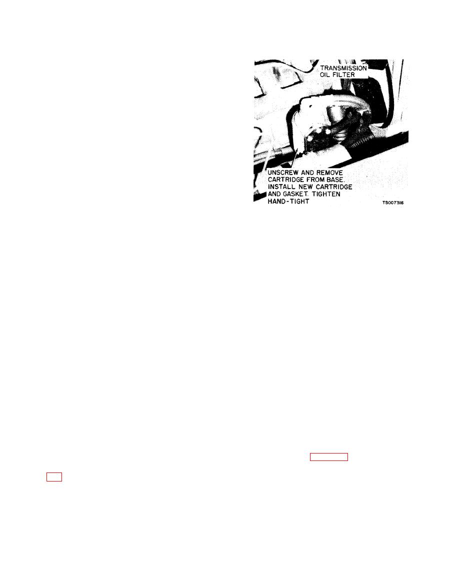
(9) Remove transmission oil filter (see figure
removed, insulators and washers m a y b e
removed.
of the way of engine removal. Remove clips from
transmission oil lines.
|
|
Privacy Statement - Press Release - Copyright Information. - Contact Us |
