 |
|||
|
|
|||
|
Page Title:
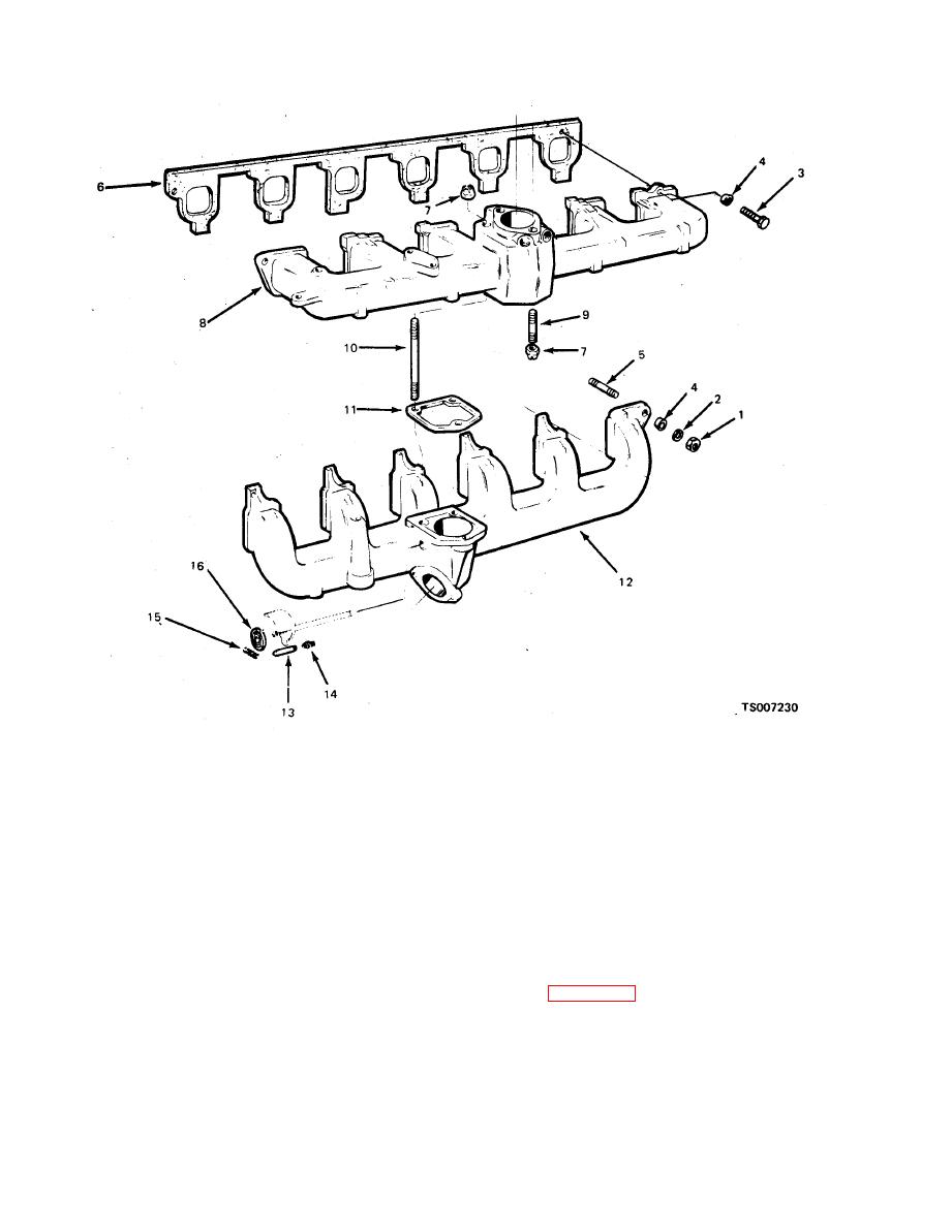
Figure 4-40. Manifolds Installation |
|
||
| ||||||||||
|
|
 TM 10-3930-633-12
1.
Nut
5.
Stud
9. Stud
13.
Pin
2.
Washer
6.
Gasket
10. Stud
14.
Spring
3.
Capscrew
7.
Nut
11. Gasket
15.
Spring
4.
Clamp
8.
Intake manifold
12. Exhaust manifold
16.
Spring
(4) Install a new intake manifold gasket.
c. Installation.
(1) Clean the mating surfaces of the cylinder
(5) Coat the mating surfaces lightly with
head and manifolds,
graphite grease. Place the manifold assemblies in
(2) If one of the manifolds is to be replaced,
position against the cylinder head. MAKE SURE
remove the tube fittings from the discarded
THAT THE GASKETS HAVE NOT BECOME
manifolds and install them in the new manifold as
DISLODGED. INSTALL THE ATTACHING
required. Also install new studs in the new
WASHERS, BOLTS AND NUTS. Torque the
manifold,
bolts and nuts to specifications in the sequence
(3) If the intake and exhaust manifolds have
shown in figure 4-41. Torque exhaust manifold to
been separated, coat the mating surfaces lightly
cylinder head bolts to 23-28 ft/lbs. Torque intake
w i t h graphite grease and place the exhaust
to exhaust manifold bolts and nuts to 28-33
manifold over the studs on the intake manifold.
ft/lbs.
Install the lockwashers and nuts. Tighten them
finger tight.
|
|
Privacy Statement - Press Release - Copyright Information. - Contact Us |
