 |
|||
|
|
|||
|
|
|||
| ||||||||||
|
|
 TM 10-3930-633-12
e. Charging System. The charging system
improper connections. Battery and ground
consists of the alternator, regulator, battery, and
connections are made at the studs on the end
ammeter. The arrangement of these components
frame.
is shown in figure 4-5. The alternator is belt
driven by the engine. Field current levels in the
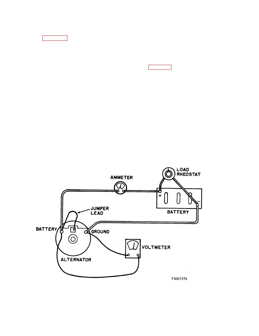
To test the output of the alternator on the vehicle,
alternator are controlled by the voltage regulator,
proceed as follows:
and are varied as required to suit battery loads
a. Place the transmission in neutral and apply
and state of charge.
the parking brake. Make the connections as
4-25. Alternator
shown in figure 4-8.
a. The alternator is an alternating current
b. Start the engine.
generator, driven by means of V-belts from the
c. Increase the engine speed to approximately
engine crankshaft damper. The alternating
2000 RPM. Turn off all lights and electrical ac-
current is rectified internally by means of diodes,
cessories.
so that alternator output is in DC current. These
d. Turn the load rheostat clockwise until 15
diodes are contained in the end frame of the
volts is indicated on the voltmeter.
alternator.
e. Observe alternator output as registered on
b. The rotor is supported at each end by ball or
the ammeter. Output should be approximately 20
roller bearings, and the rotor is dynamically
amps at an ambient temperature of 800 F.
balanced. Both end frames are equipped with
f. An output of 2 to 8 amperes below
f a c t o r y - p a c k e d grease reservoirs, which
specifications usually indicates an open diode
eliminates the need for periodic lubrication.
rectifier. An output of approximately 10 to 15
c. Installation ease is aided by a single
amperes below specifications usually indicates a
mounting lug and a slip-type field connector. The
shorted diode rectifier. An alternator with a
connector is polarized so that it can be connected
shorted diode will usually whine, which will be
only one way thus eliminating the hazard of
most noticeable at idle speed.
(1) Disconnect the battery ground cable.
(2) Loosen the alternator adjusting arm bolt,
a. Removal.
|
|
Privacy Statement - Press Release - Copyright Information. - Contact Us |
