 |
|||
|
|
|||
|
Page Title:
Service Brake Shoes and Wheel Cylinders |
|
||
| ||||||||||
|
|
 releasing adjusting nut (21), screw (20) and sleeve
b.
Inspection.
(1) Remove wheels with assembled tires (para
(22).
.
(f) Pry off brake return spring retainer (3)
from shield (7) and remove brake return spring (4).
(2) Back off brake shoe adjusting bolts and
remove brake drums.
(g) Remove brake shoe retainer (8) and
(3) Inspect thickness of lining on brake shoes.
other guide (9) from anchor (12).
Replace shoes if lining is less than 1/16 inch thick
(h) Remove brake shoes (5) from support
at thinnest point.
plate (10). Operating lever strut (6) will fall out as
brake shoes are removed.
( 4 ) Inspect wheel cylinders for leakage or
cracked or deteriorated boots. Replace cylinder if
(i) Separate operating lever (18) from
brake shoe by removing nut (19), washer and screw
defective.
c. Removal.
(17).
(1) Remove wheels with assembled tires and
(j) Spacer (11), sleeve (16), shield (7) and
tubes paragraph 4-62 a .
anchor (12) need not be removed from support
(2) Back off brake shoe adjusting bolts and
(10).
remove brake drum.
(3) Shoe installation.
(3) Clamp wheel cylinder pistons to prevent
(a) Reverse procedure in (2) above.
loss of fluid, or air entering brake lines.
(b) Turn adjusting nut (21) until brake
(4) Remove retainer (36, fig. 4-39), and brake
shoes are in released position before installing
return spring (35).
brake drum (2).
(5) Hold retainer (5) from turning, depress
(c) Be certain brake shoes are centered on
spring (6) and grap antirattle rod (7) with a pliers.
support and are free to move.
Turn 1/4 turn to release antirattle rod from backing
(d) A d j u s t b r a k e s h o e s ( s u b p a r a b ( 1 )
plate (8) and remove inner and outer retainers (5),
above).
spring (6) and antirattle rod (7).
(e) Adjust parking brake lever (subpara a
(6) Remove brake shoes (34).
(1) above).
Note. Remove wheel cylinder as described below only
if inspection shows that replacement is necessary.
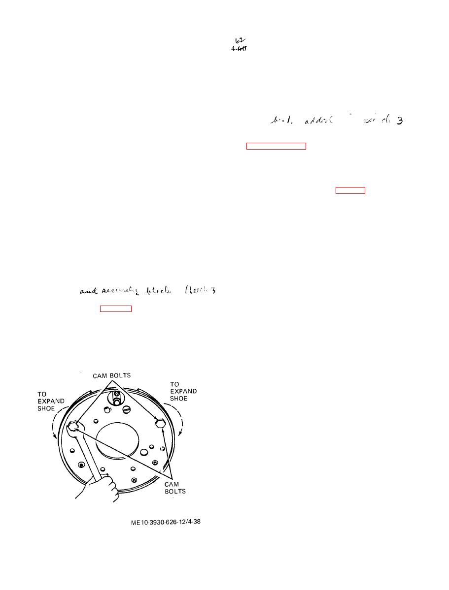
a. Adjustment.
(1) Raise rear end of tractor until rear tires
clear floor.
(2) Turn adjusting bolt with a 15/16 inch
open end wrench (fig. 4-38) until a slight drag can
be felt as the wheel is turned by hand.
(3) Back off adjusting bolt until wheel can
rotate freely.
(4) Repeat adjustment for all four brake shoes
and test brakes.
|
|
Privacy Statement - Press Release - Copyright Information. - Contact Us |
