 |
|||
|
|
|||
|
Page Title:
Figure 4-26. Cutout relay test setup. |
|
||
| ||||||||||
|
|
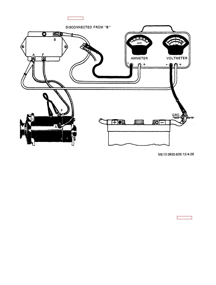 (c)
Electrical
test.
a m m e t e r reads 8 to 10 amperes, then slowly
2. W i t h e n g i n e r u n n i n g , r e g u l a t o r
decrease speed while watching ammeter. Ammeter
warmed up and battery fully charged, decrease
pointer will move to left of zero, then suddenly
engine speed until voltmeter reads less than battery
return to zero as speed is further decreased.
voltage and ammeter reads steady on zero. Cutout
relay points are now open.
Note. Opening amperage of cutout relay is the
3. Very slowly increase engine speed (by
greatest discharge reading obtained before pointer returns to
turning carburetor idle speed adjustment screw) so
zero. Opening amperage should be 3.0 to 5.0 amperes.
that voltmeter reading builds up a fraction at a
5. Repeat steps 3 and 4 several times to
time. Keep glancing at ammeter after each increase
assure, an accurate test.
in voltage.
6. If closing voltage is not within limits,
bend lower armature spring anchor (fig. 4-27). If
opening amperage is not within limits, recheck
off zero. Closing voltage should be 12.6 to 13.6 volts.
point opening (subpara (1) b) a b o v e .
4. Continue to increase engine speed until
|
|
Privacy Statement - Press Release - Copyright Information. - Contact Us |
