 |
|||
|
|
|||
|
Page Title:
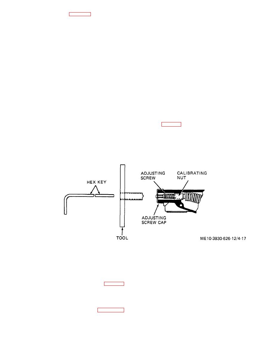
Figure 4-17. Governor adjustment. |
|
||
| ||||||||||
|
|
 When installing support (13) and pad (12), force
KEY to figure 4-16:
1. Screw
support upward so that pad is snug against tank;
2. Nut
then, tighten nuts (15).
3. Lock washer
4. Fuel sender
4-39. Governor
5. Gasket
a. General.
6. Strainer
(1) Leakage at manifold, carburetor or in-
7. Filler
t e r c o n n e c t i n g gaskets must be corrected before
8. Mounting clamp
9. Fuel tank
governor can be properly adjusted,
10. Nut
(2) Thoroughly clean governor prior to
11. Screw
making
In many cases,
any
adjustments.
12. Pad
satisfactory operation can be restored by cleaning
13. Tank support
carbon and gum deposits from governor.
14. Screw
15. Nut
(3) Start and run engine until normal
16. Shutoff valve
operating temperature is reached before making
17. Fuel tank tube
adjustments.
18. Grommet
b. Speed Adjustment.
19. Drain plug
20. Screw
21, Lock washer
( 2 ) Start and run engine at full throttle.
Tachometer should indicate 2450 rpm.
b. Cleaning.
(3) To adjust for higher speed, turn adjusting
(1) Install drain plug (19) and shut-off valve
screw cap (fig. 4-17) counterclockwise, To adjust
(16). Close shut-off valve and put one gallon SD in
for lower speed, turn adjusting screw cap clockwise.
tank and slosh it around. Pour out SD quickly
O n e complete turn of adjusting screw cap will
through fill pipe, to carry out sediment.
change engine speed approximately 300 rpm.
(2) Air dry tank interior,
c. Installation. Reverse procedure in a a b o v e .
( 6 ) Engage adjustment screw with an ap-
c. Surge Adjustment.
propriate hex key,
(1) Attach tachometer to engine.
(7) Hold adjustment screw stationary with hex
(2) Start and run engine at full throttle.
(3) Remove adjusting screw cap (fig. 4-17).
time until surge is minimized or eliminated.
(4) Fabricate tool from a short piece of metal
(8) Readjust speed if necessary.
tubing. Tubing inside diameter must exceed ad-
d. Slow action adjustment. If governor does not
justing screw outside diameter and end must be cut
cut in promptly at maximum speed or does not cut
with two tangs to engage slots in calibration nut.
out promptly at governed speed when load is ap-
Handle may be added as shown in figure 4-17 if
plied, adjust for surge (subpara. c above) except
desired.
turn calibration nut counterclockwise.
(5) Engage slot in calibration nut with tool.
|
|
Privacy Statement - Press Release - Copyright Information. - Contact Us |
