 |
|||
|
|
|||
|
Page Title:
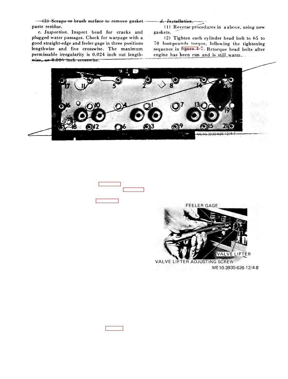
Figure 4-7. Cylinder head bolt tightening sequence. |
|
||
| ||||||||||
|
|
 s h o u l d be felt with the feeler gage when the
4-26. Valves
clearance is correct.
a. Valve Cover Removal.
(5) To increase clearance, hold valve lifter
(1) Open hood and remove right side panel
stationary and turn adjusting screw clockwise.
from engine compartment.
(6) TO decrease clearance, hold valve lifter
(2) Remove air cleaner (para 4-35 a ) .
screw
coun-
stationary
and
turn
adjusting
(3) Remove carburetor and governor (para 4-
terclockwise.
36 and 4-39).
(4) Remove manifolds (para 4-27).
(5) Remove two bolts and gaskets securing
each valve cover and remove valve covers. Remove
and discard cover gaskets and cover bolt gaskets.
b. Valve Adjustment.
(1) Crank engine by hand until scribed mark
on crankshaft pulley is aligned with pointer on
gearcase cover. At this point both exhaust and
intake valve will be open at number 1 cylinder
(lifters cannot be turned or difficult to turn with
fingers), and both exhaust and intake valves will be
c l o s e d a t n u m b e r 6 c y l i n d e r o r v i c e versa,
depending on whether number 1 or number 6 is in
firing position.
(2) If valves at number 1 cylinder are open,
adjust valve clearance at cylinders number 2, 3 and
c. Valve Cover Installation.
6. Then turn engine one full revolution and adjust
(1) Clean valve covers in SD.
valve clearance at cylinders number 1, 4 and 5.
(2) Reverse procedure in a above using new
Valve clearance on intake valves is 0.010 inch cold.
valve cover and valve cover bolt gaskets.
Valve clearance on exhaust valves is 0.016 inch
cold.
4-27. Intake and Exhaust Manifolds
(3) Insert feeler gage corresponding to ap-
a. Removal.
propriate valve given in (2) above between lifter
(1) Open hood and remove right panel from
adjusting screw and valve stem (fig. 4-8).
engine compartment.
(4) Hold lifter with one wrench and turn lifter
(2) Remove right side panel.
adjusting screw with a second wrench. A slight drag
|
|
Privacy Statement - Press Release - Copyright Information. - Contact Us |
